Privacy statement: Your privacy is very important to Us. Our company promises not to disclose your personal information to any external company with out your explicit permission.
In order to meet the requirements of different measurement objects, analog Disposable Vape, Electronic Cigarettes, vapeelectronic voltmeters are divided into various types. The basic principles of the typical three analog electronic voltmeters are described below.
1. Amplify a detector voltmeter
Amplifying a detection voltmeter is to first amplify the measured AC voltage through an AC amplifier, then add it to the detector for detection, and finally use a DC ammeter to indicate the reading. The principle block diagram is shown in Figure 3-1.

This voltmeter's AC amplifier uses a multi-stage wideband amplifier, which improves the M-watch of the voltmeter and can measure the AC voltage volts to thousands of volts, so it is also called "crystal zinc millivoltmeter ". The frequency range is mainly limited by the bandwidth of the amplifier, which can only reach several hundred kilohertz, usually as the low-frequency voltage side. There is no drift problem like DC amplifiers due to the increased sensitivity of the AC amplifier. Since the voltage entering the detector has been amplified, the nonlinearity generated by the detector diode when the detector is operating at a small signal can be avoided.
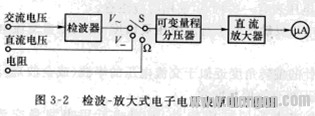
2. Detecting a magnifying voltmeterThe voltmeter first converts the side AC voltage into a DC voltage by a detector, then adds it to a DC amplifier for DC amplification, and then uses a DC micro-ampere meter to indicate the reading. The principle block diagram is shown in Figure 3-2.

The voltmeter of this structure can not only vacate the AC voltage but also measure the DC voltage and resistance. Since the amplitude is first detected and then amplified, the performance of the frequency range and the input impedance are mainly determined by the detector. In order to increase the upper limit of the side basin slave rate, an ultra-high 撅 detection diode with a small junction capacitance and a small capacitor are generally used, and the detector is made into a probe form, so that it directly contacts the side circuit. This greatly reduces the size. The influence of various distribution parameters on the high-voltage voltage location. A well-structured probe with an input capacitance of less than 1-2 pF and a measurable voltage range of several hundred megahertz. Therefore, UHF voltmeters often use this type of measurement method after first detection and amplification. Since the detector is in front of the amplifier. Due to the nonlinearity of the detector, external interference is particularly noticeable when measuring weak voltages. Therefore, the sensitivity of such a voltmeter will be limited and generally not made in millivoltmeters, with sides ranging from 0.1 to several thousand volts.
Due to the use of a DC amplifier, it will cause a zero drift. The meter will read the meter. Therefore, the stability of the electric grab voltage is relatively high, and voltage regulation measures should be adopted.
3. HeterodyneFor amplifying a detector voltmeter. Due to the contradiction between the gain and bandwidth of the wideband amplifier, it is difficult to raise the upper limit of the child's ceiling. The degree of flexibility of the detector-amplified voltmeter is limited due to nonlinear distortion and the like. In the actual side amount, it is often necessary to have voltages on the side of the field where the rate of the field is wide and the signal rate is high and the signal level is weak. The above two types of voltmeters are not competent, especially when the weak signal side stars are subject to noise and interference. limit. The spectrum of the noise is very wide, and the sinusoidal voltage on the side is single-reported. Therefore, in a certain high frequency range, the side line must have a sharp frequency selectivity in order to convert the voltages of various inclinations into a fixed frequency intermediate frequency voltage; at the same time, since the bandpass filter of the intermediate frequency amplifier can It is done very narrowly, that is, in the case of high gain, greatly reducing the influence of internal hum. The voltage side address line composed of the above principle is a heterodyne voltmeter (also called a measurement receiver).
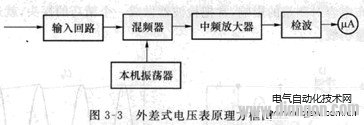
The block diagram of the heterodyne voltmeter is shown in Figure 3-3. The side voltage is passed through the input circuit (including the input attenuator and the high frequency amplifier) to nucleate the signal generated by the local oscillator in the premixer, and the medium signal is amplified, then amplified by the intermediate frequency and then detected, and finally by the DC meter. Head indication.

Since the intermediate frequency of the heterodyne voltmeter is fixed, the IF amplifier has good frequency selectivity and relatively high gain, thus solving the contradiction between the bandwidth and the gain of the amplifier. Because the IF band of the IF amplifier is extremely narrow, it can effectively reduce the influence of interference and noise while achieving high gain, and improve the sensitivity of the voltmeter to the microvolt level. Therefore, this voltmeter is also called the high frequency microvoltmeter. . If the Hamiltonian of the heterodyne voltmeter is equipped with a small loop antenna, it can also measure the leakage and radiation of the high-frequency signal generator, and even serve as a primary standard instrument for radio meters.
November 21, 2024
November 19, 2024
July 19, 2024
July 19, 2024
この仕入先にメール
November 21, 2024
November 19, 2024
July 19, 2024
July 19, 2024

Privacy statement: Your privacy is very important to Us. Our company promises not to disclose your personal information to any external company with out your explicit permission.

Fill in more information so that we can get in touch with you faster
Privacy statement: Your privacy is very important to Us. Our company promises not to disclose your personal information to any external company with out your explicit permission.